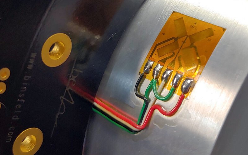
Bridges flex under traffic. Aircraft wings bend in flight. A steel beam compresses a fraction of a millimetre under a heavy load. These movements are far too small to see, yet engineers need to measure them precisely, because they reveal whether a structure is safe, a design is sound and a product will survive in the real world. The humble tool behind many of those measurements is the strain gauge. If you are learning about Strain Gauges for a project, study or purchase, this article walks through how they work, the main types, where they are used and how to choose and install them correctly.
What Is Strain?
Strain describes how much a material deforms when force is applied. It is expressed as a ratio: the change in length divided by the original length. Because the numbers are tiny, strain is often reported in microstrain, which is one millionth of a unit of length per unit of length.
Strain is closely linked to stress, which is the force acting on a material over a given area. By measuring strain and knowing the material’s properties, engineers can work out stress, load, torque or pressure.
How a Strain Gauge Works
The classic strain gauge is a thin metallic foil pattern, arranged in a zigzag grid, mounted on a flexible backing. It is bonded to the surface of the object being tested.
When the object stretches, the foil stretches with it, becoming slightly longer and thinner. This raises its electrical resistance. When the object is compressed, the foil gets shorter and wider, and resistance falls. The change is very small, so it must be measured carefully.
The key relationship is the gauge factor, which links the change in resistance to the strain. For common foil gauges the gauge factor is about two, meaning the relative change in resistance is roughly twice the strain.
Turning Tiny Changes Into Readable Signals
Because resistance changes are minuscule, strain gauges are normally connected in a Wheatstone bridge circuit. This arrangement converts small resistance differences into a voltage signal that can be amplified and recorded.
Bridge configurations include:
- Quarter bridge: One active gauge. Simple but sensitive to temperature.
- Half bridge: Two active gauges, improving sensitivity and cancelling some errors.
- Full bridge: Four active gauges, offering the highest sensitivity and best temperature compensation. It is common in load cells.
Types of Strain Gauges
Foil Gauges
The most common type, thanks to their accuracy, stability and affordability. They come in many patterns and sizes for different applications.
Semiconductor Gauges
These use silicon and offer a much higher gauge factor, making them very sensitive. They are more sensitive to temperature and can be more fragile.
Wire Gauges
An older design using fine wire. These are less common today but still used in specific cases.
Fibre Optic Sensors
Optical systems measure strain using light, with strong immunity to electrical interference. They suit harsh or long-distance monitoring.
Gauge Patterns
- Linear (uniaxial): Measures strain in one direction.
- Rosettes: Combine multiple gauges at angles to measure strain in several directions.
- Shear and torque patterns: Designed for twisting forces.
- Diaphragm gauges: Used in pressure sensors.
Where Strain Gauges Are Used
- Load cells and weighing systems: Scales in industry, retail and logistics rely on them.
- Structural monitoring: Bridges, buildings, dams and towers are checked for stress and fatigue.
- Aerospace and automotive testing: Components are validated under flight or driving loads.
- Manufacturing: Presses and machine tools are monitored for overload.
- Pressure and torque transducers: Gauges measure fluid pressure and rotating shafts.
- Biomechanics and medical devices: Researchers study forces in bones, implants and prosthetics.
- Research and education: Materials testing laboratories use them daily.
Choosing the Right Gauge
Selecting well saves time and improves accuracy. Consider:
- Measurement direction: Do you need one axis, or several?
- Gauge size: Smaller gauges suit confined spots, while larger ones average strain over a broader area, which helps on non-uniform materials.
- Resistance: Common values are 120, 350 and 1,000 ohms. Higher resistance can reduce heating and power use.
- Backing and foil material: Match the gauge to the test material and temperature range.
- Environment: Moisture, chemicals, vibration and temperature all affect the choice.
- Test duration: Short-term laboratory tests differ from long-term field monitoring.
Installation: Where Accuracy Is Won or Lost
Even the best gauge gives poor results if installed carelessly.
- Prepare the surface. Degrease, abrade lightly and clean it thoroughly.
- Mark alignment lines. Precise orientation matters.
- Apply adhesive. Use a suitable adhesive, and apply even pressure and the correct cure time.
- Attach lead wires. Use proper terminals and good soldering technique.
- Protect the installation. Coatings guard against moisture and mechanical damage.
- Check the result. Measure resistance and insulation before testing.
Common Sources of Error
- Temperature changes, which alter resistance and expand the material.
- Poor bonding, which causes drift and unstable readings.
- Lead wire resistance in long cable runs.
- Electrical noise from nearby equipment.
- Moisture getting under or around the gauge.
- Misalignment, which measures the wrong direction.
Temperature compensation, shielded cables, good protection and careful calibration reduce these issues.
Calibration and Data Handling
Regular calibration confirms that readings stay accurate. Modern data acquisition systems amplify, filter and log signals, often feeding results straight into software for analysis. Choose equipment with suitable resolution and sampling rates for your application.
Final Thoughts
Strain gauges turn invisible movement into reliable data. Understanding how they work, selecting the right type and installing them correctly will make your measurements trustworthy. Whether you are monitoring a structure, building a load cell or running laboratory tests, patient preparation and attention to detail make all the difference.